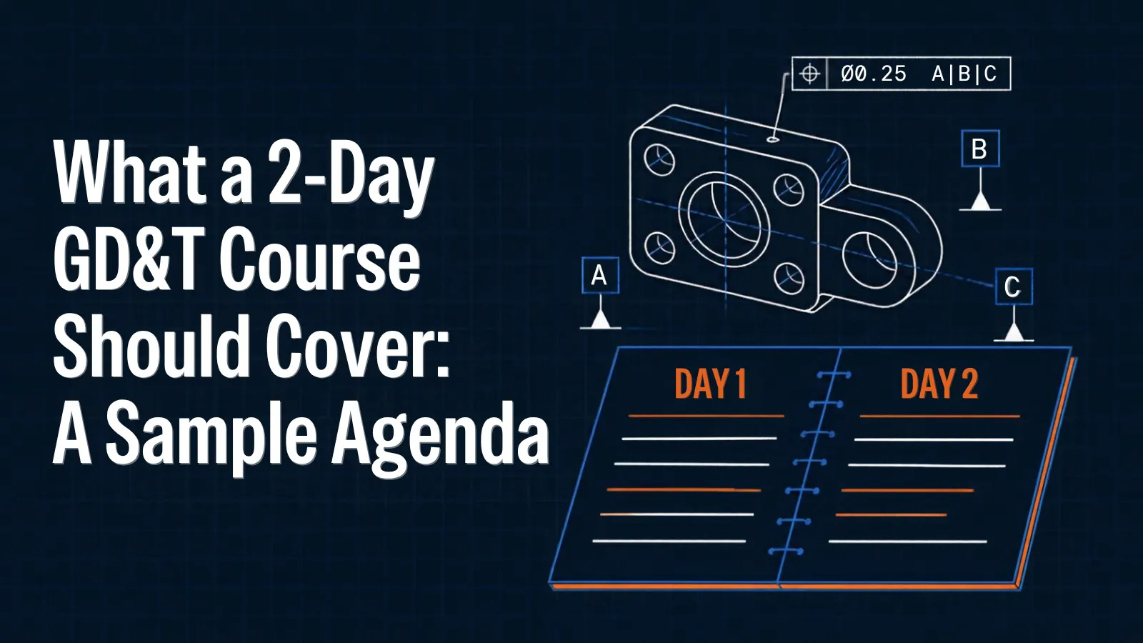
A two-day GD&T course should take a team from reading a feature control frame to applying position and profile on its own drawings, with time left to mark up real prints together. Anything less, and people leave able to name the symbols but not use them. Below is the agenda from our on-site GD&T course, session by session, with what each part should accomplish and the questions to ask any trainer before you book.
The course follows ASME Y14.5-2018, the standard most US drawings reference. ASME lists it as Y14.5-2018 (R2024), meaning it was reaffirmed in 2024 and is still the current edition.
Before day 1: the drawings
The most useful work happens before anyone sits down. Ask for a set of your team's current drawings a week or two ahead. The trainer should review them and build the exercises, questions, and examples from them.
This is the difference between a course and a lecture. Generic example parts teach the rules. Your own drawings show where your team applies them inconsistently, which is what you're paying to fix.
If your drawings are sensitive, a redacted or simplified set works well, and we can sign your NDA. Without drawings, realistic example parts still work, but the course loses some of its value.
Day 1: reading the drawing
Day 1 builds the vocabulary. By the end of it, everyone on the team should read a feature control frame the same way.
Why GD&T: what plus-or-minus tolerancing can't control
Start with the problem GD&T solves. A hole located with plus-or-minus dimensions gets a square tolerance zone, and the drawing doesn't say which surfaces to measure from. For example, a hole located within plus or minus 0.005 inch in each direction has a square zone 0.010 inch on a side. That square accepts a hole about 0.007 inch off target diagonally, in a corner of the zone, but rejects one only 0.006 inch off straight along one axis, even though the second hole is closer to where it belongs. A cylindrical position zone that just contains the square, 0.010 times the square root of 2 or about 0.0141 inch in diameter, treats every direction the same and accepts both. The datum reference frame then answers the other question: where to measure from.
The symbol set and the feature control frame
Next comes reading a feature control frame left to right: the geometric characteristic, the tolerance value (with a diameter symbol when the zone is cylindrical), any material condition modifier, and the datum references in order of precedence. Participants should practice reading frames off real drawings until it's automatic.
Datums, datum features, and the datum reference frame
Datums deserve the most time on day 1. A datum feature is a real surface or feature of size on the part. The datum is the theoretically exact plane, axis, or point derived from it. The primary, secondary, and tertiary datums build a datum reference frame that constrains the part's degrees of freedom. The practical goal is choosing datum features that match how the part mounts and functions, so design, manufacturing, and inspection all set it up the same way.
Form and orientation
Form controls (flatness and straightness, and in a full course also circularity and cylindricity) apply to a feature by itself and never reference a datum. Orientation controls (parallelism, perpendicularity, angularity) always do. A good session shows how these interact with size limits, so people stop adding form controls that the size tolerance already covers.
Exercises on your own drawings
Day 1 should end with the team reading its own prints: finding the datum reference frame, reading each frame aloud, and flagging anything unclear. That list becomes material for day 2.
Day 2: location, profile, and applying it
Day 2 is where the course pays for itself, because it covers the controls that decide whether parts pass inspection.
Position, MMC and LMC, bonus tolerance, and virtual condition
Position is the workhorse of GD&T. The session should cover basic dimensions, cylindrical tolerance zones, and the material condition modifiers. With an MMC modifier, a hole that is made larger than its smallest size gains bonus tolerance equal to that departure. Virtual condition then gives the worst-case boundary: for a hole, the MMC size minus the position tolerance, and for a pin, the MMC size plus it. That boundary is what makes a functional gage or a clearance check possible.
Profile, runout, and choosing the right control
Profile of a surface can control form, orientation, and location, depending on its datum references, which makes it the most flexible control in the standard. Runout controls a surface's variation as the part rotates about a datum axis, circular runout element by element and total runout over the whole surface. The skill to teach is choosing the right control for the function, not just reading it.
How inspection interprets the drawing
Engineers who write the drawing should understand how quality measures it. This session walks through how an inspector or CMM programmer establishes the datum reference frame from the datum features, and how an ambiguous drawing leads to different setups and different results for the same part.
Tolerance stack-ups for your assemblies
A worst-case stack-up on one of your own assemblies connects the tolerances on individual drawings to whether parts actually fit. Even one worked example changes how people assign tolerances.
Drawing review: marking up your prints together
The course should end the way good design reviews do: the team marks up its own drawings together, applying everything from both days. This is where shared conventions form, and where the team decides how it will dimension the features that cause the most questions.
What the team should keep afterward
Training fades quickly without reference material and follow-up. Our course includes handouts for every participant, a certificate of completion, and 30 days of email questions afterward, so the first real drawings after the course get checked while the material is fresh.
Questions to ask any GD&T trainer
Use the same questions for every provider you compare:
If two days is too much
The same 14 hours can run as four half days. And if your team already uses GD&T daily, the half-day refresher and drawing review may be enough: about 3.5 hours for up to 12 people, focused on your own prints. Individual engineers who need to catch up can also use one-on-one GD&T tutoring.
Book the course
Send us your team size, location, and timing, and you'll get a written proposal with dates and a final price within one business day. Request a proposal for on-site GD&T training, or see all corporate training programs.