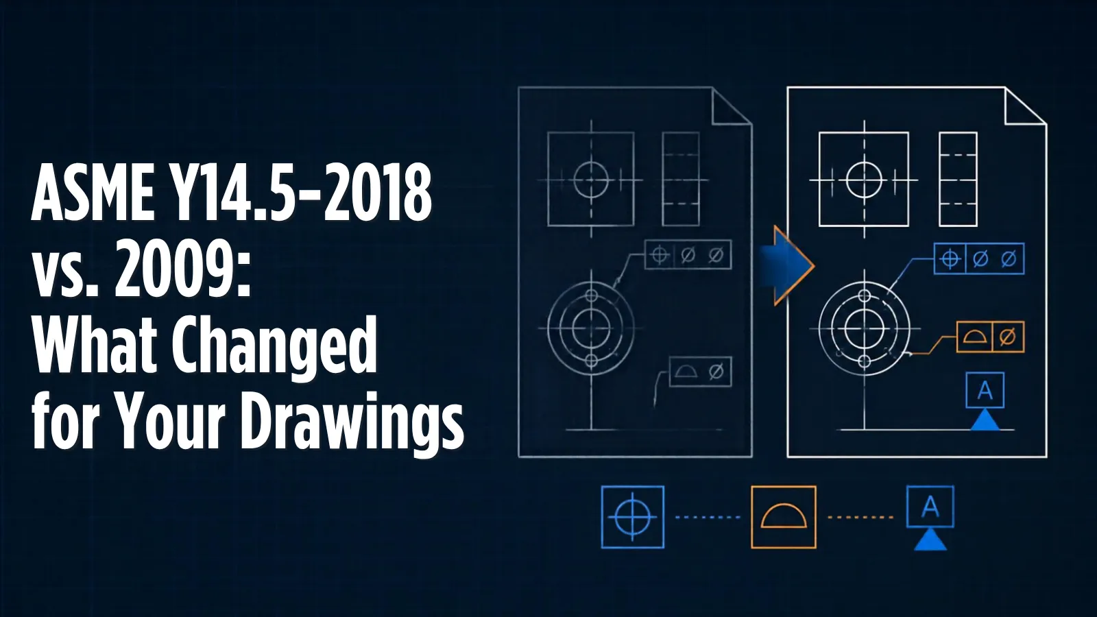
The changes from ASME Y14.5-2009 to Y14.5-2018 that show up on real drawings are short to list. Concentricity and symmetry are gone. Datum features that rock now get one default setup instead of a range of acceptable ones. Profile is the preferred way to locate surfaces, and a new dynamic profile modifier lets you tighten form without tightening size. Most of the rest is reorganization and new terms. The harder question is what to do with a drawing set that mixes both editions, and that is where this post spends most of its time.
ASME lists the current edition as Y14.5-2018 (R2024), meaning it was reaffirmed in 2024 and still replaces the 2009 edition. If your title blocks still say 2009, your drawings are not wrong. They are just read under different rules than anything new you release.
The changes you will see on a drawing
Here is the short version, limited to changes that affect what gets drawn or how a part is inspected.
| Topic | Y14.5-2009 | Y14.5-2018 |
|---|---|---|
| Concentricity | Symbol available | Removed |
| Symmetry | Symbol available | Removed |
| Datum setup when the datum feature rocks | Any of the candidate datum sets could be used | One default solution |
| Locating surfaces | Profile available | Profile emphasized for surfaces |
| Dynamic profile modifier | Not available | New symbol |
| Unequally disposed profile | Circled U or a graphical phantom-line method | Circled U only |
| Datum terms | "Datum feature simulator (theoretical)" | "True geometric counterpart" |
Each row is covered below, with what it means for the person drawing the part and the person measuring it.
Concentricity and symmetry are gone
This is the change everyone knows. Both symbols were removed, and the 2018 Foreword explains why, as quoted by GD&T Basics: other characteristics "provide more direct control of features and establish requirements that have a well-defined meaning," and removing the symbols "does not leave the industry without a means to control coaxial or symmetrical features."
Both controls worked on median points. To check concentricity, an inspector had to find the midpoints of opposed points around a diameter and see whether they all fell inside a cylinder around the datum axis. That is slow to measure and rarely what the designer meant. Most of the time the real requirement was "this diameter must run true" or "this hole must be centered."
What to use instead depends on the function:
These are not one-for-one swaps. Runout includes form error, so a 0.002 inch runout tolerance is usually a tighter requirement than a 0.002 inch concentricity tolerance on the same feature. Position controls the axis of the feature's actual mating envelope, not a cloud of median points. Changing the symbol changes the requirement, so it should be an engineering decision, not a find-and-replace.
One default setup for datums
When a primary datum feature is not perfectly flat, the part can rock on its datum simulator. Y14.5-2009 allowed any of the resulting candidate datum sets to be used. Y14.5-2018 replaced that with a single default. As GeoTol summarizes it, "the part is to be adjusted to a single solution that minimizes the separation" between the datum feature and its true geometric counterpart.
This matters most on cast, molded, or welded parts with rough datum surfaces. Under 2009, a borderline part could pass in one setup and fail in another, and both setups were legitimate. Under 2018, inspection and your supplier should reach the same setup. If you have a part that goes back and forth between pass and fail depending on who measures it, check which edition the drawing references before arguing about the CMM program.
Profile for surfaces
ASME describes the 2018 edition as one that "emphasizes the use of profile for location tolerances applied to surfaces". Position still applies to holes, pins, slots, and tabs. For a flat face that must sit at a basic distance from a datum, profile of a surface is the 2018 way to say it.
The standard also moves further away from plus-or-minus dimensions between features. GeoTol notes that the fundamental rule changed from "each dimension shall have a tolerance" to "each feature shall be toleranced." In practice that means locating features with basic dimensions and a geometric tolerance, not with a chain of plus-or-minus dimensions that leaves the measuring origin open.
Dynamic profile
The dynamic profile modifier, a small triangle placed after the profile tolerance, is new in 2018. Tec-Ease describes it as a way to let profile go all around a feature while controlling only form, not size.
For example, a molded boss might need its size held to 0.010 inch but its shape held to 0.002 inch. Before 2018 you had to tighten the whole profile tolerance to get the tighter shape. With dynamic profile, a second profile segment refines the form while the boundaries are free to grow or shrink with size.
Terms and presentation
Some changes show up only in the words people use. The 2018 edition went back to the term "true geometric counterpart" for the theoretically perfect datum simulator, and GeoTol lists the 2009 phantom-line method for unequally disposed profile as discontinued in favor of the circled U.
The standard itself got longer, from 214 to 326 pages according to GD&T Basics, mostly because figures moved to the end of each section and many now include model views. Form, orientation, and profile each have their own section, so if your team's training notes cite section numbers from 2009, those references no longer line up.
How to manage a mix of 2009 and 2018 drawings
Most companies that have been releasing drawings for more than a few years have both editions in the vault. That is normal. The rule to build everything else on is simple. A drawing is read under the edition it references, usually in the title block or a general note. As GD&T Basics puts it, "Unless a drawing title block references the 2018 ASME Y14.5 standard, concentricity can be used." A concentricity callout on a 2009 drawing is still a valid requirement, and inspection should measure it the 2009 way.
From there, a few practices keep a mixed set under control.
Know what you have
Pull a list of active part numbers with the Y14.5 edition each drawing references. Flag three groups: drawings that reference 2009, drawings that reference an older edition such as 1994, and drawings that reference no edition at all. The last group is the real risk, because nobody can say for certain which rules apply.
Update drawings when they are revised, not all at once
Rewriting every legacy drawing to 2018 is expensive and rarely worth it for parts that are stable and passing inspection. A common approach is to move a drawing to 2018 when it is revised for another reason. When you do, the edition change is itself a design change. Every concentricity and symmetry callout needs a replacement chosen for function, and the new drawing should be reviewed like any other change.
Do not mix editions on one drawing
A drawing that references 2018 should not carry a concentricity symbol, and a drawing that references 2009 should not use dynamic profile. If a revision adds a 2018-only tool, update the edition reference and review the whole drawing against it.
Tell inspection and suppliers which edition applies
Your CMM programmers and suppliers need to set up datums and interpret callouts the same way you do. For 2009 drawings, agree on how rocking datums will be handled. For 2018 drawings, confirm their software and procedures use the single-solution default. A short line in the purchase order or quality requirements pointing to the drawing's referenced edition prevents most disputes.
Train people on both
Your engineers need to write 2018 drawings and still read 2009 ones correctly. Training that covers only the current edition leaves people guessing on the legacy drawings they see every day. For how this fits into a full course, see what a 2-day GD&T course should cover.
A quick check for any drawing you pick up
Before you interpret or change a drawing, ask these in order:
Get your team on the same edition
Our on-site GD&T course teaches ASME Y14.5-2018 on your own drawings, and the drawing review covers the legacy prints your team works from, including how to replace concentricity and symmetry when a drawing is updated. Teams that already use GD&T can use the half-day refresher and drawing review instead: about 3.5 hours for up to 12 people, at $2,500. For one engineer who needs to catch up, there is one-on-one GD&T tutoring.
Request a proposal for on-site GD&T training, or see all corporate training programs.